

Simple Designs
The simplest form of solar panel regulator would be to use a LM317 Voltage regulator IC or something alike . The voltage regulator IC can be set to regulate at 13.8V. Then the voltage will never rise above 13.8V and the battery will be well protected at 25°C. However, doing this will shunt away a somewhat significant portion of the current at all times which could have charged the battery. To get better charge efficiency one could use a shunt regulator which will only start shunting away current when the battery terminal voltage has reached 13.8Volts. A simple shunt regulator is easy to make and low cost.
An unverified theory of mine is that when a solar panel is in the sun and no current is drawn from it that it will degrade faster than when used ( ie when current is drawn ). The reasoning behind this is as follows: Solar panels convert photon energy into electrical energy. If the photon energy can not be converted into electrical energy ( which can only happen when the solar panel is connected to a current drawing circuit ) some of the photon energy is rather converted into heat. This extra heat might cause some damage.
For this reason I prefer shunt regulators since a shunt regulator will always draw current from the solar panel even when the battery is fully charged and not drawing current. Because it will shunt the current away.
Here is the circuit diagram for a basic op amp shunt regulator ( click to enlarge):
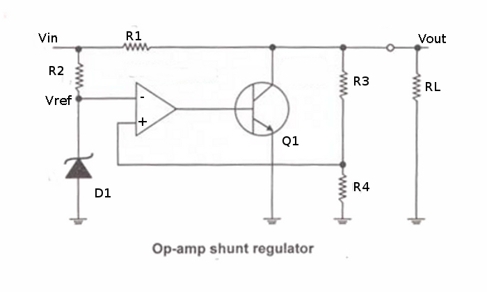
I include this circuit just for simplification, clarification and explanation. The actual practical circuit with component values for the solar panel regulator will follow soon. And has added components.
The solar panel will be connected to Vin. The zener D1 will set the – terminal reference voltage of the comparator ( op amp ) to some value and R2 will protect the zener from to much current. When the voltage at the + terminal of the comparator is above the reference voltage on the – terminal, the comparator output will jump from about 0 V to a high voltage which will cause the transistor Q1 to switch on. This action will cause the transistor to shunt current away from the load Rl ( which would be the battery ). The voltage across rce ( resistance collector emitter of the transistor) will then drop according to the voltage divider network rce and R1. Which would cause the voltage on the + terminal of the comparator to drop. When it drops below the voltage on the – terminal the comparator will output a low voltage switching off the transistor. And when the voltage rises again the cycle is repeated. This is how this basic shunt regulator manages to regulate the output voltage to the load ( or battery ). This switching happens very fast and the output voltage remains virtually constant.
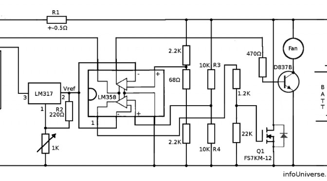
Of course its best to have a very low value for R1 so it does not diminish the current flowing into the battery (RL by much). I simply use a bit of coiled up thick copper wire as R1.