

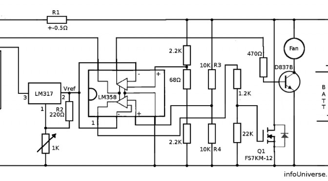
In order to make the output voltage adjustable I have used an adjustable voltage regulator LM317 to apply an adjustable reference voltage to the – terminal of the comparator. With a pot. Lets have a look at my circuit diagram:
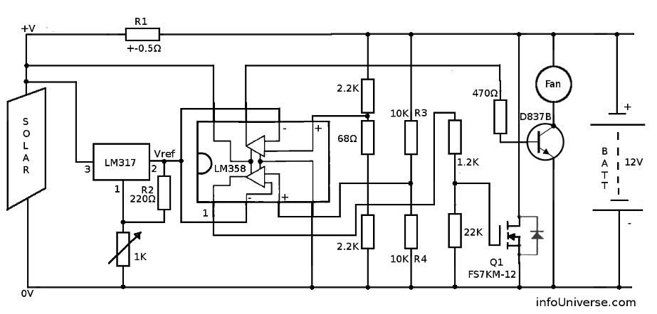
I designed this diagram with components I could find on my scrap heap. Since the LM358 had two comparators I decided to use both and dedicate the other one to driving a fan via a transistor. The fan cools down the heat-sink onto which I mounted the MOSFET. You could use any transistor or MOSFET able to handle the current your panels will push. Alternatively one could also put the heat-sink in water in order to use the excess energy ( when the battery is fully charged ) to heat up water :). Coffee ?
My transistor arrangement for the voltage on the + terminal of the comparator which drives the transistor for the fan, is such that the fan would actually come on a slight bit before the regulator would actually start regulating. I have been unable to explain with certainty why the fan would at times not come on without this arrangement.
I have used this circuit for many years. I just manually adjust the regulating voltage according to the ambient temperature.
Using an off the shelf commercial Solar Charge controller has many benefits. I suggest you read up on them and consider the costs etc before venturing off into making your own.
Have fun and good luck.